Welcome to the user manual for the Arduino Simulator. Whether you’re a beginner or advanced user, this documentation should cover almost everything you need to know about the simulator.
Getting started with the simulator is easy and it won’t take long to learn the basics, but if you need any help or just want to find out more about a particular feature, then these guides are for you.
Choose a Arduino Simulator manual
Arduino IO Simulator 1.5.2
Windows
Arduino IO Simulator Drag & Draw 1.2
Windows
Arduino IO Simulator 1.5.3
macOS
Simulator usage
The Arduino IO Simulator gives you the tools and components you need to simulate your Arduino IO. It’s made for quick tests and small projects, there is still further developed in order to obtain the widest possible IO functions.
This Arduino IO Simulator is designed to test an Arduino program quickly with the Arduino board without really having connections to external IO (buttons, potentiometers, LEDs, LCD displays, ...).
To use the simulator you need 3 programs:
- Java JRE
- The Arduino Simulator software
In order to use the Simulator, you need to download the Java JRE on our computer.
The Arduino Simulator for macOS needs the Java JDK.
License activation
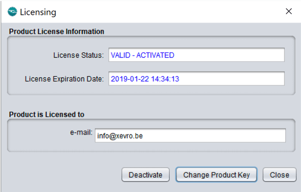
The first time you opens the program there will be a license activation screen popping up where you can enter and activate the license key. The Arduino Simulator Drag & Draw is available for 30 days free or you buy a lifetime license.
Click on the ‘Change Product Key’ to insert the license key you copied on the website, after entering this you need to click on ‘activate’.
When you want to change the trial as a paid version just replace the license key by clicking on the ‘Change Product Key’. After entering the license key you can activate the key with the ‘activate’ button.
License FAQ
What do I need to do with the license key?
The license key shown on the page of the Arduino IO Simulator Drag & Draw is a 30-day free trial version. Download the Arduino Simulator setup, the first time you open the simulator, a message appears stating that no key has been inserted. Click on 'Change product key' and insert your purchased key or trial key. To register the key click on 'Activate'.
I'm getting an "ACTIVATION_SERVER_CONNECTION_ERROR", what should I do?
Turn off your firewall, the Arduino Simulator can't connect to the server because of the firewall protection.
I'm getting an "ACTIVATION_NOT_FOUND_ON SERVER_ERROR", what should I do?
if you tried to deactivate your purchased license you can contact us, we help you out!
I'm getting a "MISMATCH_HARDWARE_ID" error message.
Try to turn off your firewall.
If this doesn't work go to 'C:\Users\"User Name"\AppData\Roaming’ and search for a file called “MyAppKey.lic” and delete that file.
Make sure you type in the password correctly. The best way is to copy and paste the license key.
Simulator FAQ
Arduino IO Simulator Drag & Draw
On what operating systems does the Simulator run?
The Simulator runs on every modern Windows PC. A Windows XP computer needs an older version of Java, the newer versions of Java doesn’t work because XP is no longer supported.
Which version of Java do I need?
The most recent version of Java, Java 7 and Java 8 work as well with the Simulator.
The Arduino Simulator for macOS needs a Java JDK. Tested with JDK 1.7 and 1.8.
Now Java stops with support for the JDK license, what will we do?
JavaFX will be removed from the Java JDK (Java Developers Kit) as of JDK 11, which is due in September 2018. It is bundled in the current JDK 9 and will remain in JDK 10, due this spring. Commercial support for JavaFX in JDK 8 will continue through at least 2022. Featuring a set of packages for graphics and media, JavaFX has been part of the JDK download since 2012.
We are currently developing our applications with the Java JDK software provided by Oracle. We use JDK 8 and because Oracle will stop publishing free JDK updates, we will be able to develop our application up to JDK 10. newer JDK versions will not be used to develop our applications.
I have a sensor that isn't provided in the Simulator, what now?
If the sensor is controlled with an IO instruction like digitalWrite or analogRead… that is supported by the Simulator, you just use the IO instructions and change the first letter with a capital letter. Look at this page below for more information about the instructions. You can always send me an e-mail with a suggestion for a sensor you like if it's possible to add it you can update and use it.
I can't upload to the Arduino board
One of the problems can be the fact that you are still connected to the Simulator software. Make sure you are disconnected from the Arduino board when you want to upload the Arduino code with the Arduino IDE. If that's not the problem, you might search online for a solution.
What's the difference with an Arduino Simulator and an Arduino IO Simulator?
An Arduino Simulator is capable of simulating an Arduino board without having one. The Arduino IO Simulator uses an Arduino board and the serial connection to simulate the IO commands.
I can't open the simulator, I'm getting a 'Could not find main class: Simulatoruno, program will exit" message.
In order to run the simulator, you need to have minimum Java version 7. If you have an older version it won't start and give you this message. Update your Java version to the newest version available.
The simulator software shuts down unexpectedly
Try these troubleshooting steps.
Arduino IO Simulator 1.5... Windows & macOS
On what operating systems does the Simulator run?
The Simulator runs on every modern Windows PC and Apple MacBook, iMac,... A Windows XP computer needs an older version of Java, the newer versions of Java does n’t work because XP is no longer supported.
Which version of Java do I need?
The most recent version of Java, Java 7 and Java 8 work as well with the Simulator.
The Arduino Simulator for macOS needs a Java JDK. Tested with JDK 1.7 and 1.8.
What to do if you get this error message:
Unable to access jarfile/Applications/ArduinoSimulatorMacOS.app/Contents/dist/ArduinoUNOsimulator.jar
You didn't place the simulator in the right folder. Drag the 'ArduinoSimulatorMacOS.app' to the “Applications" folder and open it there so the simulator has the right directory to work properly.
Arduino Simulator library codes
The Arduino IDE works with instructions that the IO reads and writes, we must convert this to serial communication, so we made a library that does this for you.
We don’t want to change the real instructions so we decided to make the first character as a Capital, the instructions with a point in it are changed with no point.
Example 1:
digitalWrite(12, HIGH);
Becomes DigitalWrite(12, HIGH);
Example 2:
lcd.print(“Hello world”);
Becomes lcdprint(“Hello world”);
Instructions Arduino IDE Instructions Arduino IO Simulator
digitalWrite(x,y); DigitalWrite(x,y)
digitalRead(x); DigitalRead(x);
analogWrite(x,y); AnalogWrite(x,y);
analogRead(x); AnalogRead(x);
myservo.write(x); myservowrite(x);
Serial.print(x); Serialprint(x);
tone(x,y ,z); Tone(x,y ,z);
noTone(x); NoTone(x);
lcd.setCursor(x,y); lcdsetCursor(x,y);
lcd.print(longx); lcdprint(x);
lcd.print(“x”); lcdprint(“x”);
lcd.autoscroll(); lcdautoscroll();
lcd.noAutoscroll(); lcdnoAutoscroll();
lcd.clear(); lcdclear();
lcd.display(); lcddisplay();
lcd.noDisplay(); lcdnoDisplay();
lcd.blink(); lcdblink();
lcd.noBlink(); lcdnoBlink();
lcd.write(x); lcdwrite(x);
lcd.rightToLeft(); lcdrightToLeft();
lcd.leftToRight(); lcdleftToRight();
lcd.home(); lcdhome();
lcd.cursor(); lcdcursor();
lcd.scrollDisplayLeft(); lcdscrollDisplayLeft();
lcd.scrollDisplayRight(); lcdscrollDisplayRight();
DHT11 sensor DHTread11(pin number);
myservo1.write(); myservo1write(); first servo of the 2 simulator servos
myservo1.attach(); myservo1attach(); first servo of the 2 simulator servos
myservo2.write(); myservo2write(); second servo of the 2 simulator servos
myservo2.attach(); myservo2attach(); second servo of the 2 simulator servos
myKeypad.getKey() mykeypadgetKey(); keypad code
How to simulate the IO step by step
Connect the Arduino board
Change the original code to the Arduino Simulator code (see examples)
Connect the Arduino Simulator to the right COM port and simulate your project
Write your own code and add the Arduino Simulator library
Select the in- and outputs in the Arduino Simulator (drag & drop in Arduino Simulator Drag & Draw)
1. Connect the Arduino Board
The Arduino Simulator works with a lot of Arduino boards:
Only the digital and analog pins that are available on the Simulator can be used!
Disconnect the Arduino Simulator before uploading the Arduino code with the Arduino IDE.
2. Upload your custom Arduino code with the corresponding library file
Open the Simulator and go to 'Help -> Arduino UNO programming code -> Arduino UNO programming code (Ino)'.
This will open an Arduino (ino) file with the corresponding library and important code in it.
3. Change the original Arduino code
In order to let the Simulator understand the code, we have devised our own instructions. To maintain usability, we have decided to change the current instructions a little bit and replace only the first letter with a capital letter. We have modified the instructions with a point so that the point may be omitted. The simulation principle is the same with all our Arduino Simulators, the only differences are the options and more IO features.
digitalWrite(13, HIGH); -> DigitalWrite(13, HIGH);
lcd.print("x"); -> lcdprint("x");
4. Select the used in-outputs in the Arduino Simulator
Each input and output on the Simulator has a selection box where the used digital or analog pin can be connected.
With the Arduino Simulator Drag & Draw it's possible to draw lines, different shapes or add texts with custom fonts on it to make it easier to simulate your projects.
5. Connect the Arduino Simulator to the Arduino board with the right COM port
The Arduino Simulator knows which port is the Arduino board
Upload the code from the Arduino IDE to the Arduino board.
Make sure the Arduino is disconnected while uploading the Arduino code.
Arduino Simulator Draw & Draw IO
LEDS
There are 14 LEDs available, for every pin of the Arduino 1 led. Use the combo box to connect it with the Arduino. By clicking on the led you can change the color.
The LEDs can be controlled with the DigitalWrite() function.
Buzzer
The buzzer is used to make a noise with a custom frequency. The combo box is used to connect the buzzer with the Arduino. Click on the clock to resize the buzzer and hide the settings.
The buzzer can be controlled with the DigitalWrite(); function. By sending out a DigitalWrite(pin, HIGH); signal in the Arduino code, the buzzer will make a noise with the adjustable frequency.
Relay
There are 2 relays to simulate a relay contact. The combo box is used to connect the relay to one of the 14 IO pins. The cross button is used to set the relay back to its original place in the tab pane. Click on the relay itself to resize and hide the combo box settings.
The relay can be controlled with the DigitalWrite() function.
Buttons
There are 8 buttons available. The combo box is used to connect the button to one of the 14 IO pins.
The cross button is used to set the button back to its original place in the tab pane. Click on the ‘…’ to resize and hide the combo box settings. The light blue pin can be used to hold down the button while doing other things, the border changes to red when it's pressed.
The buttons can be controlled with the DigitalRead() function.
Square wave
The squarewave sends pulls signals to the Arduino, when the signal is high you see the grey square lights up ‘red’. The combo box is used to connect the square wave to one of the 6 analog pins (A0-A5 = D14-19).
The cross button is used to set the square wave back to its original place in the tab pane. When you click on the ‘SquareWave’ button there opens a second window with a slider to change the frequency.
The square wave can be controlled with the DigitalRead() function.
Motion detection
The motion sensor sends signals to the Arduino every time there is a movement (click on the sensor image), when the signal is high you see the gray square lights up red. The combo box is used to connect the motion sensor to one of the 14 digital pins. Use the ‘…’ to resize and hide the settings. The cross button is used to set the sensor back to its original place in the tab pane.
The motion sensor can be controlled with the DigitalRead() function.
DHT11 sensor
The DHT11 simulates the temperature and humidity. The combo box is used to connect the sensor to one of the digital pins (D2-13); The cross button is used to set the sensor back to its original place in the tab pane. The 2 sliders are used to change the value of the temperature (°C) and humidity (%).
The DHT sensor can be controlled with the DHTread11(pin) function. Use the DHT11 example to test this.
Noice detection
The noise detection is used to send an analog (0-1023) signal to the Arduino depends on the noise level. The combo box is used to connect the noise detector to one of the 6 analog pins (A0-A5).
The cross button is used to set the noise detector back to its original place in the tab pane. When you click on the ‘Start Noise Detection’ the detection starts listening to the microphone noise level. When the noise level exceeded the slider value then it will send the signal (0-1023) to the Arduino. The limit value in the Arduino code needs to be lower than the noise detection slider because the signal will be sent when the noise is detected.
The noise detection can be controlled with the AnalogRead() function.
Sliders
There are 3 sliders to connect with one of the 6 analog pins (A0-A5). The cross button is used to set the slider back to its original place in the tab pane. The green rectangle shows the place you can click on to hide the combo box and make the component smaller. The value is sent to the Arduino after releasing the mouse when changing the slider, if you click on the small circle the Simulator will send constant values to the Arduino.
The sliders can be read by the Arduino with the AnalogRead() function.
7-segment display
The 7 segment display has 7 digital pins that can connect to D0-6 on the Arduino. The display can be connected in common anode or common cathode. The cross button is used to set the display back to its original place in the tab pane.
To light up the display-use DigitalWrite(D0-6);
See the example: Parking
Tone Melody
The tone melody can be connected to digital pin D8 of the Arduino. The cross button is used to set the tone melody back to its original place in the tab pane. The frequency and time of the sound (milliseconds) are present in the light green boxes.
Use Tone(8, f, d); and NoTone(8); (See example: Tone Melody)
NoTone() stops playing sound.
f = frequency
d = duration
Bargraph
The bargraph can be connected to one of the 6 digital PWM pins of the Arduino. The cross button is used to set the bargraph back to its original place in the tab pane. The bargraph shows the % of your value (0-1023), this can be used to simulate a PWM signal as a % bar. By clicking on the bargraph itself you can resize it and hide the combobox to make it smaller.
Use AnologWrite(pin, value); to control the bargraph (See example: sound switch, use the restore function to get the IO already dragged into the worksheet).
Sound generator
The sound generator can be connected to one of the 6 digital PWM pins of the Arduino. The cross button is used to set the sound generator back to its original place in the tab pane.
By clicking on the sound box image you can resize it and hide the combo box to make it smaller. By changing the time (ms) you change the duration that the sound goes off(1ms – 10 000ms). The frequency can go from 10hz to 10Khz.
Use AnalogWrite(pin, value); to control the sound generator.
Servo
There are 2 servos that can simulate a servo wheel with just one digital pin (D2-13) of the Arduino. The cross button is used to set the servo back to its original place in the tab pane.
The number of degrees (°) is visible in the servo. Click on the servo to make the servo smaller through removing the background and combo box. With the Myservo1Write() you can control servo. Myservo2Write() is used for the second servo.
Motor wheels
There are 2 motor wheels that can turn left and right with just 2 digital pins of the Arduino. To adjust the speed use one of the 6 PWM pins of the Arduino. The cross button is used to set the motor wheels back to its original place in the tab pane. By clicking on the wheel itself you can hide the background and combo boxes. If you use only the PWM signal, you can send positive and negative signals to the motor wheel to turn left or right.
To control the motor wheels you need to use DigitalWrite() and AnalogWrite().
See the Wheels example.
Barrier
The barrier works also like the servo with one signal (D2-13). The cross button is used to set the barrier back to its original place in the tab pane. By clicking on the barrier itself you can hide the background and combo box.
Use Myservo1Write() to control the barrier.
Webcam detection
The webcam motion detection can be used to send a high signal by motion detection through the webcam. The combo box is used to connect the webcam detection to one of the digital pins (D2-13) of the Arduino.
The cross button is used to set the webcam detection back to its original place in the tab pane. When you click on the ‘play’ button the webcam input will be visible in the black area of 160x120. The grey square will light up ‘red’ when the movement is detected.
The webcam motion detection can be controlled with the DigitalRead() function. The webcam motion detector will send a signal to the Arduino when there a movement detected.
Keypad 4x4
Connect the keypad to the Arduino by pushing the ‘Connect D2 to D9’ button. The cross button is used to set the keypad back to its original place in the tab pane.
Use mykeypadgetKey() to control the keypad (see example: keypad password).
LCD Display 16x2
The LCD display can be connected to the Arduino by 2 modes. Connect D2-5, D11, and D12 or use the I2C option (A4-A5). The cross button is used to set the LCD display back to its original place in the tab pane. All the instruction that controls the LCD are changed by removing the ‘.’ point.
example: lcd.print() = lcdprint().
RGB LED
The RGB led can be connected to the Arduino by 3 PWM pins. Connect 1 of the 6 PWM pins to each color value (R, G, B). The cross button is used to set the RGB led back to its original place in the tab pane. Click on the led itself to hide to settings. Each color represents a value of 0-255 which indicates a 0-255 color. Note: the 3 sliders are scaled to 0-1023.
To control the RGB led you use AnalogWrite().
analogWrite() = AnalogWrite().
RGB Slider
The RGB led can be connected to the Arduino by 3 analog pins. Connect 1 of the 6 analog pins to each color value sliders (R, G, B). The cross button is used to set the RGB slider back to its original place in the tab pane.
Use the ‘RGB_Led’ example and the ‘RGB-Led.sav’ (restore settings) to test the RGB led with the sliders.
To control the RGB slider you use AnalogRead().
analogRead() = AnalogRead().
Stepper motor 28-BYJ48
The Stepper motor can be connected to the Arduino by 2 or 4 digital pins (8, 10, 9 and 11). The driver module (ULN2003) is processed in the simulator. There are 4 LEDs that indicate which coil is energized on which specific moment in time. The amount of steps and degrees is shown next to the 4 LEDs.
The cross button is used to set the stepper motor back to its original place in the tab pane. You can find the stepper motor under the ‘More I/O’ button.
The simulator stepper motor has 2 input fields:
- Sim_SPEED
- Sim_STEPS
Steps = 1 to 2048 (360°)
Speed = 1 to 200
Input Steps -> Sim_STEPS
Input Speed ->Sim_SPEED
Use the ‘Stepper.sav’, ‘StepperMotorControl.sav’ and the ‘StepperMotorKnob.sav’ example (restore settings) to test the stepper motor.
If you are using the stepper motor and also the serial monitor together, it’s possible you will get a warning that will tell you to close the serial monitor and reset the Arduino because you are losing steps.
More information about the stepper motor can be found on this page and in the user manual of the Arduino IO Simulator Drag & Draw.
Serial Monitor
In the simulator, it’s now also possible to view the serial data. There are 2 buttons that you can use to send a signal to the Arduino. The monitor shows you a ‘Receive from Arduino’ line when the Arduino sends data to the simulator and a ‘Send to Arduino’ line will be shown when you send something to the Arduino with the simulator.
If you want to save the serial monitor output you can save the whole text or a selected area.
With the search function, it’s possible to search for a specific word or character. if the word or character is found, it will be highlighted in yellow. By clicking on the blue question mark you get the explanation of all the simulator codes.
By using Serialprint(); in the Arduino IDE, you can send a serial message.
The serial message will start with ‘txt_’ in the serial monitor.
© Copyright 2019. Xevro.be All Rights Reserved.